Often perceived carburetor problems are actually the result of using improper procedures. So, applicable procedures are documented here.
Starting Procedure
- Engage emergency brake by pulling back on it.
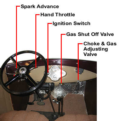
- Push lever left of steering wheel (Spark Control) all the way up (Retard)
- Pull lever right of the steering (Hand Throttle) half way down
- Turn Gas Valve under dash on passenger side to open (Pointing down)
- Turn Choke Control Valve (under right side of dash) full clockwise and back off 1/4 turn. If it's quite cold out, it may be better to open a full turn.
- Turn Ignition Switch on (Clockwise)
- Push in clutch and put Transmission in Neutral
- Pull Choke Control Out
- Turn engine over 3 Revolutions – Choke in on 3rd Revolution
- When Engine Starts – Push Throttle Lever (Right Lever) Up
- Put Left Lever all the way down. (Depending on how your engine is timed, 3/4 down might be better.)
- Allow Engine to Warm Up. (The accelerator pedal will need to be used to keep engine running until it warms up.)
- Turn Choke control (actually GAV) clockwise to smoothest operating condition.
- When starting an engine, which is already warmed up, omit Choke steps.
- Always put Left Lever (Spark Retard Position) all the way up when starting & then down when driving.
- Have Fun Driving!
Shut Down Procedure
- Engage emergency brake by pulling back on it.
- Push Left Lever (Spark Control) all the way up (retard position)
- Push Right Lever (Throttle) all the way up
- Turn Gas Valve under dash on passenger side to closed position (pointing to the Left). If vehicle is going to be left over night, or similar circumstances, it's a good idea to let the engine burn up the majority of the gasoline in the carburetor by letting engine run until it stalls.
- Turn Off the Lights and any other Accessory
- Turn Ignition Switch off (Counter Clockwise)
Carburetor Idle RPM and Idle Air Mixture Adjustment

- There are two external carburetor adjustments, and they affect only the idle performance. They are the idle RPM and idle air mixture adjustments
- Turn Gas Valve under dash on passenger side to open (Pointing down)
- Preparation: Fully warm the engine up, move spark control (on left side of steering wheel) up, turn the under dash choke control knob full clockwise and then counter clockwise about one turn, and move the hand throttle lever (on the right side of the steering wheel) all the way up. If engine tend to die, pull the throttle lever down a little.
- Preliminary Idle RPM adjustment: Turn the adjusting screw on the carburetor throttle arm until the end of the threads is making contact with the stop. You should now be able to put the hand throttle lever all the way up without the engine tending to die. Go back to the adjusting screw on the carburetor throttle arm and adjust it to a low RPM, just faster than where engine tends to stall. This will ensure that the carburetor idle circuit if functioning.
- Idle Air mixture adjustment: Slowly turn the idle air mixture screw clockwise until the engine begins to stall, and note the position. Slowly turn the idle air mixture screw counter clockwise until the engine begins to stall and note the position. Now, adjust the screw about half way between the two positions, and you will often hear a very slight increase in engine RPM. (Idle air mixture screw should be about 1–1/2 turns out from full clockwise.)
- Final Idle RPM adjustment: Pull the spark lever about 3/4 down. Readjust the idle RPM adjustment for the idle speed that you prefer. (If adjusted too high, you will likely tend to grind gears when driving.)
Using Carburetor to Check Engine Timing
- Increase engine speed to twice that of idle RPM by pulling down the throttle lever at the steering column.
- Gradually open the gas adjusting valve 1/2 to 1 full turn. The engine should start to run richly, and some smoking at the exhaust may occur. This verifies that the fuel passage, regulated by the Gas Adjusting Valve, is open. Turn the GAV clockwise until the engine RPM returns to where it was previously
- Slowly pull the spark lever down. Engine RPM will increase up to a point. When the maximum RPM is achieved, note this as the position where you will want to place the lever for normal driving purposes.
- Raise the throttle lever up to the top of its travel. The engine should idle smoothly. With the spark lever still in its "ideal" position for everyday driving, go around the car to the carburetor and ram the accelerator control rod (i.e., from the accelerator linkage) forward. The engine should accelerate to maximum speed within about two seconds if the engine timing is correct. Don't hold the accelerator rod in this forward position for more than a few seconds, because you could damage your engine. If the engine accelerates smoothly and without stumbling, your idle and ignition settings are correct.
- If acceleration of engine speed is slow or sluggish, ignition timing is probably somewhat retarded. Move the spark rod up to the top of its travel, and adjust the timing. Once the timing has been adjusted, restart the engine, pull down the throttle rod until engine RPM is twice idle RPM, and return to step 3.
Adjusting Engine Timing
- Before adjusting the engine timing, ensure that the breaker point contacts are in good shape and the gap is set to .016 - .020 inches. Also, verify that the rotor gap to the distributor body contact points is between .030 to .035 inches.
- Turn ignition key off.
- Place gear shift lever in neutral position.
- Fully retard spark lever on the steering column.
- Screw out timing pin located in timing gear cover and insert opposite end of pin into the timing pin hole.
- With starting crank, turn the engine over slowly while at the same time pressing in firmly on the timing pin. When the piston #1 reaches the top of the stroke, the timing pin will drop into a small recess in the timing gear.
- Remove the distributor cap, body, and rotor, and loosen the distributor cam locking screw until cam can be turned.
- Connect a test light probe between the breaker point arm and an engine ground.
- Turn ignition switch on.
- Turn cam in counter clockwise direction until the breaker points are fully open (light comes on), then slowly turn the cam back in a clockwise directions until the points just close (light goes off). Next lock the cam by securely tightening the cam locking screw. Be careful not to move cam position, while tightening the screw.
- Slowly pull down on spark advance lever. The test lamp should come on (points open) when the lever is about 3/4 down. Sometimes steps must be repeated until distributor cam is properly set.
Removing Carburetor From Vehicle
- Turn gas shut off valve to off position and run engine until engine stalls, having used up most of the gasoline in the carburetor.
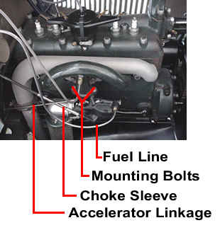
- From passenger side of engine, disconnect throttle linkage (which is spring loaded) from the carburetor.
- Disconnect choke rod from the carburetor by pushing up sleeve (set aside sleeve and spring).
- Disconnect fuel line from the carburetor with either at 1/2" or 9/16" wrench.
- Remove two mounting bolts with a 1/2" wrench.
- When lifting carburetor out of the engine compartment, use caution so as to not drip gasoline onto the fender.
Disassembly of a Zenith Model A Ford Carburetor
- Remove Main Bolt and pull castings apart. If the two halves do not pull apart by hand, it is mostly likely due to a stuck Venturi. To separate casting halves, fully seat a six-inch long, hex head bolt and lightly strike bolt head with a hammer a few times. If castings are badly rusted and corroded, they may need to be thermal shocked to loosen parts and threads. After making sure that all gasoline is completely evaporated from carburetor, try heating with a torch, but do not get them too close to cherry red. Be careful with small brass parts and soft metal Venturi. After thermal shocking, repeat the earlier steps in this paragraph to separate the casting halves.
- Try to remove all parts using hand tools.
- If Venturi is stuck in one of the castings, use Venturi Extraction Tool.
- To remove the idling jet, use Drilled Out 9/32 Nut Driver.
- To remove Gas Adjusting Valves (GAV), which have the special 13/32" head, use Gas Adjusting Valve Wrench.
- Dig out and discard all old gaskets.
- Remove hidden brass Gas Adjusting Valve Seat and gasket washer, if they were used in your vintage of lower casting.
- Look for rusted Filter Strainer tips that may need to be dug out of upper castings.
- Drill out brass passage plugs from both castings.
- Inspect Castings.
ˆ Top of Page • Drain Plug • Gaskets • Secondary Well • Idle Air Adjustment Needle Valve • Float Valve and Float • Venturi • Idle Jet • Castings • Upper Casting Passages • Dremel Stone #911 • Throttle Shaft Bushing Drill Fixture Plate • Gas Adjusting Valve Seat Honing Tool & Guide
Installing Heli-Coils
- Drill out damaged threads with recommended drill size (for mounting flange use 21/64").
- Use Heli-Coil tap supplied with kit, to cut oversize threads for coil insert.
- Screw insert onto the mandrel, of provided tang, until driving tang is fully engaged in slot.
- With mandrel, screw insert into tapped hole until insert is 1/4 to 1/2 turn below top surface.
- Trim off excess wire.
Lower Carburetor Casting Assembly
- Screw in Compensator Jet, using two gasket washers, with screwdriver.
- Screw in Seat for Gas Adjusting Valve (if your vintage of casting needs one), with a Gasket Washer, using a screwdriver.
- Screw in Main Jet, using one gasket washer, with screwdriver.
- Screw in Cap Jet, using one gasket washer (with 5/16" nut driver).
- Screw in drain plug, with one gasket, using 1/2" wrench.
- Screw in Secondary Well until it bottoms out, but do not tighten, with screwdriver.
- Screw Gas Adjusting Valve housing (minus the needle) into the casting. Tighten with a 7/16 or 13/16" wrench.
- Screw Gas Adjusting Valve needle into the Gas Adjusting Valve housing. It does not need to be screwed in very far at this time.
- Slide choke driver over Gas Adjusting Valve assembly.
- Attach choke lever arm to choke shaft with a lock washer and an 8/36 nut.
- Slide choke shaft into casting and align choke lever cam into choke driver.
- Attach Choke plate into shaft, using 2 oval 5/40 screws. Care should be taken to remove as much choke level arm cam engagement slop as possible.
- Screw Choke Driver to full clockwise position, and then back off about 1/4 of a turn.
- Drop Venturi into casting.
- Install main bowl gasket over Venturi onto the casting.
- Set aside a main bolt and lock washer, which will later be used to attach the lower casting assembly to the upper casting assembly.
ˆ Top of Page • Cap Jet • Float Valve and Float • Idle Air Adjustment Needle Valve • Main Jet • Filter Strainer • Compensator Jet • Drain Plug • Opening GAV does not provide extra fuel at low speeds
Upper Carburetor Casting Assembly
- Insert throttle shaft into casting and attach throttle plate to the shaft with 2 oval 5/40 screws. Turn Idle RPM adjusting screw on throttle arm so that throttle plate remains slightly open when it is closed.
- Position cap and spring onto idle air mixture screw and then screw it into the casting. Initial setting of the idle air mixture screw should be 1-1/2 turns from full clockwise.
- Screw in Filter Strainer, with a gasket washer, using a 5/8" wrench.
- Screw in Float Valve with appropriate gasket washer thickness.
- Attach Float with Float Hinge Pin.
- Screw in Idle Jet, with no gasket washer as it is designed for a taper fit. Use Drilled Out 9/32 Nut Driver.
- Attach Upper Casting Assembly to Lower Casting Assembly, with Main Bolt and lock washer, using appropriate 1/2 or 9/16" wrench.
Installing Carburetor Onto Engine
- A carburetors fuel supply must be clean and unrestricted. No matter how well a carburetor has been restored, if the fuel supply is dirty or restricted the carburetor will soon not function properly.
- The carburetor should be installed with the vehicle outside in the open air.
- Loosely attach carburetor to engine intake manifold, using gasket, and lock washers with two 5/16-18 bolts that are 3/4" long. Do not yet tighten.
- Connect the choke rod, spring, and sleeve to the choke driver. This is done by sliding spring and sleeve up the rod until rod can be connected to the driver, and then release spring tension.
- Connect throttle linkage, which is spring loaded, to the carburetor throttle arm.
- Inspect ferrule on the fuel line for any damage and that the ferrule is not more than 3/16" from the end of the line. If the ferrule has been deformed to fit a carburetor casting with a damaged fitting seat, it needs to be replaced. If ferrule is more than 3/16" from the end of the fuel line, the line can press against the Filter Strainer causing a fuel flow restriction. So, the ferrule will need to be replaced. To ensure that a new ferrule is properly position, I insert a 1/2-20 by 3/4" long bolt into the Filter Strainer hole. Then when line and ferrule are tightened into place, the ferrule is forced to be in the proper position.
- Connect the fuel line to the carburetor, tightening it with either at 1/2" or 9/16" wrench.
- When a carburetor has been lying on its side, the float can catch on the side of the casting. It is suggested that carburetor be shaken just before installation. When a carburetor is first installed on an engine and the vehicles fuel shut off valve is opened the first time, a carburetor may leak gasoline initially because the float has stuck. It is important that when fuel shut off valve is opened this first time, one must observe the carburetor for the first 30 seconds to see if it leaks. Be prepared to tap the carburetor on its most forward end several times with a small hammer or other object to cause float valve to seat properly. The leak should stop in a few seconds and not reoccur.
Testing Newly Installed Carburetor
- Start engine using Starting Procedure.
- After the engine has warmed up, perform Carburetor Idle RPM and Idle Air Mixture Adjustment.
- Test drive vehicle to verify that engine idles well, engine accelerates without hesitation, engine does not stall with quick stops, engine does not backfire, and re-verify that carburetor does not leak. It's a good idea to do test drive by driving around town, at highway speeds, and if possible on a long, slow, steep climb.
- If problems are experienced, see Problem Solving.